Even though the Bridge was drawn up on Solid-Works and is part of our Mechanical Drawings, I have decided to show it in the Architectural Part of this Blog since it has many features indicative of an Architectural drawing.
When me and my partner decided to sketch our bridge, we wanted to do a simple design that would incorporate the structural integrity of a spherical shape. We played around with egg shapes, circles, half circles, and other arcs, but in the end we decided that a "Half Circle" would offer the most support to what we wanted to do with the project.
Our goals outlined by our teacher, Perry Charmichael, were simple. It must not have more than 5 cubic inches of material, it must span a 12" gap (with 1/2 inch platform on both sides of the bridge), and it must support as much weight as possible.
We these criteria in mind we set out to make the best bridge we could. Here is how we did it.

First, we decided on our half round shape. We wanted to draw up something in Solid-Works to see how much material we needed to work with, and to see what we could do. When we sketched this, it was just to get a feel for what we were up against.
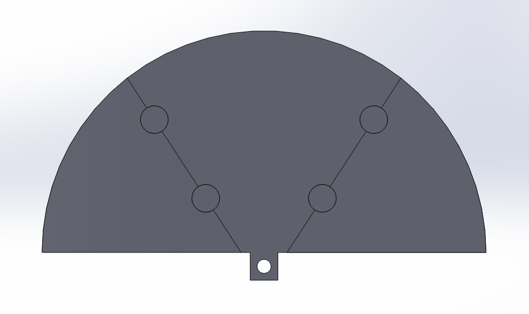
This is a sketch of our piece with added support and a proposed (weight holding pin hole) added. At this point we knew this was the design, we just needed to take some weight off of it.

Next, we split the piece apart and ended up with our center piece. From here we could manipulate it separately and play with it while keeping the other pieces in tact.

This is the beginning sketch of our side piece. derived from the half circle we were able to work with this piece on its own and change it to our needs.


Above is a preliminary sketch and part we decided to use for maximum structural integrity.


Here is where we started to take some mass off of our side piece. We wanted to keep the structural integrity while making it with the least amount of material possible. To the right is a proposed design for our cross member train track platform.

To the right is our finished design for the bridge center piece. Our bridge included a total of 2 center pieces. You can see in this model, we added structural support between each separate arch in this design. We also added rigid support around the outside of this piece to add to the integrity as weight would be dispersed along the external edge of this piece.


To the left is the final design for the side piece. Our bridge included a total of 4 side pieces. In this model, just as we did with the center piece; we added structural support between each separate arch in this design, as well as, added rigid support around the outside of this piece. To further stabilize this structure we added support ribs so that the center piece could easily slip into place. There is a "butt plate" located bottom right. This plate was added to prevent horizontal distortion "Compression", due to stress being applied. The hole at the bottom right was made to house a connection rod. This rod was added to prevent opposing horizontal stress "Pulling", also connecting both side pieces to each other.
________________________________________________________________________________
Solid-Works has an interesting design feature; it allows you to do "stress analysis" on any part or assembly with relative ease. Below are some of the results we got when we did stress analysis on our bridge. Pieces were assembled in Solid-Works, Material used in stress testing was (ABS plastic), Point of stress(es) were the inside bottom half of the two center piece pin hole circles (located towards center), Fixtures: one side of the bridge was held in place, while the other side was allowed to slip. Here are the results.

Displacement Study:
Our first study, with 100 lbs of force (total), yielded 0.079 inches of displacement. Our tolerance for the specifications were 0.100 inches of displacement. So at this point we were well within our operating parameters.

Factor of Safety:
The results we received from our factor of safety test surprised us as much as the displacement study. We found our bridge had an overall factor of safety of 4.9, with the range being from (5.4-2.9). The percentage was dramatically higher towards the upper end of the spectrum which was also a pleasing result.

Von Mises (PSI):
Shown to the right is the Von Mises psi distortion and what the bridge would look like due to the pressure if it was applied at these separate locations.

Deformation:
To the left is a graphic representation of what would happen to the bridge under a huge amount of strain, where it is most likely to fail, and what types of deformation and bending should occur and where. When the actual video of the bridge was taken (under stress), It did begin to bend in such a shape as this, but not as elaborate as depicted here.
Bridge Drawings

To the left is the final drawing of the center piece. It includes all relative dimensions and can be replicated on any Solid-Works work station.

To the right is drawing (1 of 2) of the 4 side pieces. It also can be duplicated on any Solid-Works work station. Pay particular attention to how it might be drawn as every drawing has a key to the way it can be drawn the easiest.
Below is the second drawing to the side piece. This drawing had to be added due to constraints on printer paper. We could only use size A, or size B paper. This drawing has correct dimensions for the side ribs and the placement for several important center-lines.

Finished Assembly
This is our full Assembly (with BOM call-out)
Results: We took 1st place in overall bridge weight holding capacity (out of 5 bridge designs). Made of ABS Plastic, our bridge held 46 lbs with 0.1 inch of deflection.

No comments:
Post a Comment